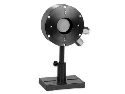
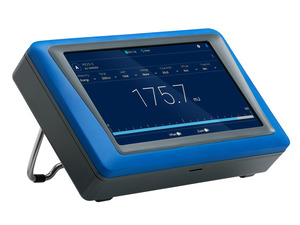
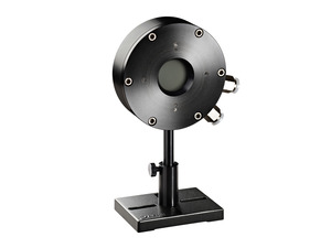
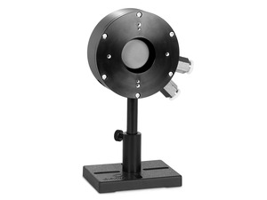
The 1000W-BB-34 thermopile sensor is a water cooled laser power and energy thermal sensor with a 34 mm aperture. It can measure optical power from 5 to 1000 W and energy from 400 mJ to 300 J. It has the spectrally flat broadband BB coating and covers the spectral range from 0.19 to 20 µm.
Broadband 0.19 to 20 µm absorber
Water-cooled for 5 to 1000 W average power measurement
Additional drawings are not available for this product.
Specifications
Product Name
1000W-BB-34
Absorber Type
BB - Broadband general purpose
Aperture Size
Ø34 mm
Spectral Range
0.19-20 µm
Minimum Power
5 W
Maximum Average Power
1000 W
Minimum Pulse Energy
400 mJ
Maximum Pulse Energy
300 J
Response Time
2.5 s
Maximum Average Power Density
7 kW/cm²
Maximum Energy Density <100 ns
0.3 J/cm²
Maximum Energy Density 2 ms
10 J/cm²
Cooling
Water
Dimensions
Ø100 x 35 mm
Cable Length
1.5 m
CE Compliance
Yes
UKCA Compliance
Yes
China RoHS Compliance
Yes
Features
Choosing a Thermal Sensor
In this short “Basics” video we review the use – and selection - of thermal sensors for measuring low, medium and high laser powers.
Sensors for Measuring Laser Power
In this short "Basics" video we review in general how one goes about measuring laser beam power, so that you'll have a clear understanding of what the different sensor types are, and when to use each type.
Measuring Ultra High Power Laser Beams
Laser beams with powers of many tens of Kilowatts are becoming more and more common in today's applications, industrial as well as research. This video will discuss the technical challenges in measuring such lasers, and will show you a range of solutions now available from Ophir for measuring up to 100KW -- safely, and accurately.
Water Cooled Sensors: Things to Look Out For
Water cooled sensors are commonly used when measuring laser beams of more than a few hundred watts. In this video, you will learn about some critical issues you need to consider when using water cooling, such as water temperature, water flow rate, and corrosion prevention.
Thermal Sensor Calibration
As the spectral sensitivity of the absorber used for the power and energy measurement is not fully linear, Ophir sensors get a high precision calibration by default with more than one wavelength.
Each thermal sensor is calibrated independently of a particular Ophir power meter with its calibration information contained in the DB15 plug. When the sensor is connected to the meter, the meter reads and interprets this information to display a calibrated reading. Each power meter is calibrated independently and has the same sensitivity as an other meter within about 2 tenths of a percent.
Unless otherwise indicated, Ophir sensors and meters should be recalibrated within 18 months after initial purchase, and then once a year after that.
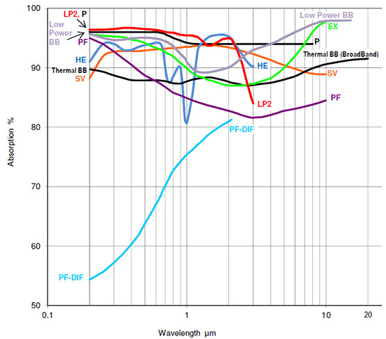
Absorption of different thermal sensor absorber types
The Ophir specification on accuracy is in general 2 sigma standard deviation. This means, for instance, that if we list the accuracy as +/-3%, this means that 95% of the sensors will be within this accuracy and 99% will be within +/-4%. For further information on accuracy see calibration procedure tutorial.
First, clean the absorber surface with a tissue, using Umicore #2 Substrate Cleaner, acetone or methanol. Then dry the surface with another tissue. Please note that a few absorbers (Pyro-BB, 10K-W, 15K-W, 16K-W and 30K-W) cannot be cleaned with this method. Instead, simply blow off the dust with clean air or nitrogen. Don't touch these absorbers. Also, HE sensors (such as the 30(150)A-HE-17) should not be cleaned with acetone.
Note: These suggestions are made without guarantee. The cleaning process may result in scratching or staining of the surface in some cases and may also change the calibration.
In theory, if a beam is completely parallel and fits within the aperture of a sensor, then it should make no difference at all what the distance is. It will be the same number of photons (ignoring absorption by the air, which is negligible except in the UV below 250nm). If, nevertheless, you do see such a distance dependence, there could be one of the following effects happening:
If you are using a thermal type power sensor, you might actually be measuring heat from the laser itself. When very close to the laser, the thermal sensor might be “feeling” the laser’s own heat. That would not, however, continue to have an effect at more than a few cm distance unless the light source is weak and the heat source is strong.
Beam geometry – The beam may not be parallel and may be diverging. Often, the lower intensity wings of the beam have greater divergence rate than the main portion of the beam. These may be missing the sensor's aperture as the distance increases. To check that you'd need to use a profiler, or perhaps a BeamTrack PPS (Power/Position/Size) sensor.
If you are measuring pulse energies with a diffuser-based pyroelectric sensor: Some users find that when they start with the sensor right up close to the laser and move it away, the readings drop sharply (typically by some 6%) over the first few cm. This is likely caused by multiple reflections between the diffuser and the laser device, which at the closest distance might be causing an incorrectly high reading. You should back off from the source by at least some 5cm, more if the beam is not too divergent.
Needless to say, it’s also important to be sure to have a steady setup. A sensor held by hand could easily be moved around involuntarily, which could cause partial or complete missing of the sensor’s aperture at increasing distance, particularly for an invisible beam.
If the power is P and the diameter of the beam is D then the power density is P /(.785 * D2) . If it is a pulsed laser and the energy is E, the repetition rate is R and the diameter is D then the power density is E*R/(.785 * D2), The energy density is E/(.785 * D2). The sensor finder will automatically calculate the power and energy density.
Ophir meters and sensors are calibrated independently. Each meter has the same sensitivity as the other within about 2 tenths of a percent. Each sensor is calibrated independently of a particular meter with its calibration information contained in the DB15 plug. When the sensor is connected to the meter, the meter reads and interprets this information. Since the accuracy of our sensors is typically +/-3%, the extra 0.2% error that could come from plugging into a different meter is negligible and therefore it does not matter which calibrated meter we use with a particular calibrated sensor.
The damage threshold of thermal sensors does depend on the power level and not only the power density because the sensor disc itself gets hotter at high powers. For instance, the damage threshold of the Ophir broadband coating may be 50KW/cm2 at 10 Watts but only 10KW/cm2 at 300W. The Ophir specifications for damage threshold are always given for the highest power of use of a particular sensor, something which is not done by most other manufacturers. This should be taken into account when comparing specifications. The Sensor Finder takes the power level into consideration when calculating damage threshold.
Corrosion is caused by interactions between the metallic components of the sensor and the cooling water, which may contain a variety of dissolved ions. Many factors affect the risk of corrosion forming, but the most important are the pH and the mixture of ions in the water. For this reason, we recommend using neutral deionized water in a closed circulating system (pH between 6 and 8). Please note that deionized water is usually slightly acidic (pH 5.65) due to absorption of CO2 from the atmosphere. The cooling water can be neutralized by adding 5 ml of a 10 mM solution of NaOH for each liter of water in the cooling system. Commercial additives such as Optishield Plus are also recommended for systems such as ours that have copper and aluminum in them. Optishield has the additional benefit of having biocide to prevent buildup of organic contamination.
To prevent corrosion it is also crucial to not allow standing water to evaporate inside the sensor when it is not in use. When disconnecting a sensor from the cooling system, the water channel should be cleared by blowing compressed air through it.
For those customers still experiencing problems with corrosion, we recommend the new thermal sensor 1000WP-BB-34 which has a special design in which all materials that come into contact with the cooling water are either copper or nonmetallic.
You can find a lot more information about the correct use of water-cooled sensors in the article "How to use water cooled Ophir sensors", here.
Many factors affect the risk of corrosion forming, but the two most important are:
the mixture of ions in the water
the water’s pH
Our current recommendation is to use DI water – but of a neutral pH. DI water is usually slightly acidic; it can be titrated to a neutral pH, using a bit of sodium hydroxide for example. There are also commercial additives that can help prevent corrosion, for instance Optishield Plus. For a more detailed discussion, see the FAQ at https://www.ophiropt.com/laser--measurement/knowledge-center/faq/7805
You can find a lot more information about the correct use of water-cooled sensors in the article "How to use water cooled Ophir sensors", here.
We don’t supply chillers, nor insist on specific models; the only important thing from our point of view is to simply keep to the requirements specified for the cooling water of the specific model of sensor, such as minimum flow rate at full power, water temperature range, and - more important than the actual water temperature - water temperature stability. The temperature of the water should not be changing by more than 1 deg/min (because changes in water temperature could cause heat flow in the sensor which would be detected as if it were laser power, and cause errors in the reading).
Metric water fittings for all water cooled sensors except 16K-W & 30K-W with quick connection to 10mm plastic tubing. The Metric water fittings are also suitable for the QBH Adapters. Replaces standard fitting connecting to 3/8" tubing (set of 2 each).
Compare
Description
Compatibility
Drawings, CAD & Specs
Avail.
Price
7Z08353Metric Water Connector, 10 mm, Water Cooled Sensors
UNIVERSAL
In Stock
$29.00
Showing 1 to 1 of 1 entries
Thermal Sensor Cables
Order a cable of a different length along with the sensor to receive a cable other than the standard 1.5 m length.
Compare
Description
Compatibility
Drawings, CAD & Specs
Avail.
Price
7E01122AThermal Sensor Cable, 3 m Length, Connect to Power Meter
The SH to BNC Adapter allows the connection of an Ophir sensor to a current or voltage measuring device for measurement of the raw sensor analog output. A current meter should be used for photodiode sensors. Current or voltage meters can be used for thermal sensors.
Compare
Description
Compatibility
Drawings, CAD & Specs
Avail.
Price
7Z11010BNC Adapter, DB15 Optical Sensor Connector
UNIVERSAL
8 Weeks
$92.00
Showing 1 to 1 of 1 entries
Extended Warranty for Sensor
Customers that purchase the above items also consider the following items. Ophir-Spiricon meters and sensors include a standard manufacturers warranty for one year. Add a one year Extended Warranty to your meter or sensor, which includes one recalibration.
In order to provide better service and products, please provide the following brief information. Any future resource requests will be automatically available.
Password Reset
Enter your email address below to reset your account password.
Password Reset
Email Verification Required
Cart Items Updated
Remove Product
Remove this product from your comparison list?
Check Order Status
Provide an order number and postal code to check the status of an order or download an invoice for an order that has shipped. Login to view your complete order history.
Sign In Required
To access this and other valuable technical resources, please sign in or register for a new online account.