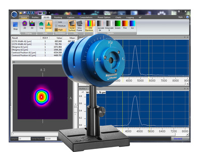
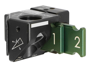
The NanoScan™ 2s Si/3.5/1.8 scanning-slit profiling system accurately captures and analyzes wavelengths from 190 to 1100 nm with its Silicon detector. It features a 1.8 µm slit size suitable for small beams, near real-time data capture rates, an optional power measurement feature, and operates in CW or kHz Pulsed modes which makes it ideal for comprehensive analysis of UV, Visible, and NIR lasers.
3.5 mm aperture for beam sizes from 7 µm to 2.3 mm
Power levels from 10 nW to 10W
Silicon detector covers 190 to 1100 nm spectral range
USB 2.0 interface
NanoScan Standard or Professional software included
NanoScan Standard is our full-function software with a extensive set of NIST traceable ISO beam width and roundness, beam position, and M2 measurements and a customizable under interface with the ease-of-use and flexibility that customers have come to expect.
NanoScan Professional has all of the functionality that NanoScan Standard includes. NanoScan Professional supports all of our scanning slit profilers, but includes an automation interface written in ActiveX to push data to your custom applications.
Specifications
Product Name
NanoScan 2s Si/3.5/1.8
Sensor Type
Silicon Photodetector
Spectral Range
190 to 1100 nm
Slit Size
1.8 µm
Aperture Size
3.5 mm
Beam Size
7 μm to 2.3 mm
Scanhead Size
83 mm
Power Range
10 nW to 10 W
Communication
USB 2.0
CE Compliance
Yes
UKCA Compliance
Yes
China RoHS Compliance
Yes
Features
NanoScan 2s Slit Profiler Demonstration
Fundamentals of Laser Measurement & Beam Profiling
Is your laser's beam profile shaped correctly for your application? This video teaches the fundamentals of laser beam profiles and discusses the benefits of profiling your laser beam. Several case studies are presented showing before and after laser beam profiles.
Why Measure Your Laser Beam?
This tutorial is presented by Ophir-Spiricon sales engineers - the experts in the field of measuring lasers and in helping you get the most out of your laser beam.
The detector is mounted internal to the NanoScan behind the rotating slits. This position is not important to the measurements. The measurement plane is the scan plane of the slits, which is nominally 0.74 mm ±0.025 mm from the Reference Surface on the front of the NanoScan. Please refer to the mechanical drawings in Appendix B of the NanoScan Operational Manual.
This is usually caused by the Automatic ROI selection. After acquiring the beam, you should then uncheck the Auto ROI in the ROIs menu and the beam should stabilize.
The silicon detector is very transparent to NIR light >1000 nm. If it is used for measuring these beams, you will often see a tailing profile, because the signal does not decay fast enough. This will lead to erroneous results. We recommend using the germanium, or if there is enough power, the pyro electric detector for these wavelengths.
This means that the motor is not able to set the rotation speed to within 0.01% precision. This typically means that the motor is wearing out, or that something is causing the motor to not be able to rotate at a constant speed. This typically requires that the system come back to the factory for inspection and repair.
The NanoScan V2 product is great for looking at focused spots, but sometimes the C-Mount ring that is on the front can get in the way mechanically. By removing the three retaining screws it will allow you to remove this ring so you can get mechanically closer to the front of the NanoScan V2. Care should be used when removing these screws and the ring so something does not fall down inside the input aperture of the NanoScan V2. It is recommended that if you are going to remove the C-Mount ring that you invert the NanoScan V2 so it is looking at the floor and then remove the screws and the C-Mount ring to allow gravity to work in your favor and pull them away from the input aperture.
Actually, only one NanoScan can be run from the NanoScan software at a time. If you did connect multiple NanoScans, only one will be recognized and able to run, and the other(s) will not be selectable.
Yes, the NanoScan Automation Interface is the same between older versions of the application and the most current version. Installing the latest version of the NanoScan V2 application will not break your Automation Interface. You will need to run the NanoScan V2 application one time before attempting to use your Automation Interface again, though. This is to establish the connection with the hardware and the NanoScan V2 application again after the upgrade, so the Automation Interface will be able to get the data from the NanoScan V2 application.
In order to provide better service and products, please provide the following brief information. Any future resource requests will be automatically available.
Password Reset
Enter your email address below to reset your account password.
Password Reset
Email Verification Required
Cart Items Updated
Remove Product
Remove this product from your comparison list?
Check Order Status
Provide an order number and postal code to check the status of an order or download an invoice for an order that has shipped. Login to view your complete order history.
Sign In Required
To access this and other valuable technical resources, please sign in or register for a new online account.